Difference between revisions of "File:Project-structure.png"
Jump to navigation
Jump to search
(uploaded a new version of "File:Project-structure.png": Arrow direction: make A --> B mean 'A invokes B' Resolution: 720 px to fit the main content column Colors: nicer) |
(Mkii --> Mark II) |
||
| (One intermediate revision by the same user not shown) | |||
| Line 1: | Line 1: | ||
| − | ConTeXt project structure as flow chart | + | ConTeXt project structure as a flow chart |
| − | + | Here is the complete code. Note that this is [[Mark II]] code, and so must be compiled with {{code|texexec}}. If somebody more experienced with the chart module can give separate colors to the project, product, component, and environment boxes, that would be excellent. | |
| − | < | + | <texcode> |
| + | \usemodule [chart] | ||
| + | \setupcolors [state=start, system=rgb] | ||
| + | |||
| + | \definecolor [green] [r=.720, g=1, b=.72] % pale green | ||
| + | \definecolor [pink] [g=.720, r=1, b=.72] % pale red | ||
| + | \definecolor [blue] [g=.720, b=1, g=.72] % pale blue | ||
| + | |||
| + | \setupFLOWcharts | ||
| + | [height=4\bodyfontsize, | ||
| + | maxwidth=\textwidth, | ||
| + | offset=none] | ||
| + | |||
| + | \setupFLOWlines | ||
| + | [corner=rectangular, | ||
| + | color=black] | ||
| + | |||
| + | \setupFLOWshapes | ||
| + | [framecolor=black, | ||
| + | background=color, | ||
| + | backgroundcolor=green] | ||
| + | |||
| + | \startTEXpage | ||
\startFLOWchart[projekte] | \startFLOWchart[projekte] | ||
| − | + | \startFLOWcell | |
| − | + | \name {project} | |
| − | + | \location {3,3} | |
| − | + | \connection[rl] {environment1} | |
| − | + | \text {\ssb Project} | |
| − | + | \stopFLOWcell | |
| − | + | \startFLOWcell | |
| − | + | \name {environment2} | |
| − | + | \location {5,2} | |
| − | + | \text {\ssb Product-specific \\ environment} | |
| − | + | \stopFLOWcell | |
| − | + | \startFLOWcell | |
| − | + | \name {environment1} | |
| + | \location {5,3} | ||
| + | \text {\ssb Project-wide \\ environment} | ||
| + | \stopFLOWcell | ||
| − | + | \startFLOWcell | |
| − | + | \name {product1} | |
| − | + | \location {1,1} | |
| − | + | %\connection[tb] {comp11} | |
| − | + | %\connection[ptb] {comp12} | |
| − | + | \location {2,2} | |
| − | + | \connection[ntb] {comp11} | |
| − | + | \connection[tb] {comp12} | |
| − | + | \connection[btn] {project} | |
| − | + | \text {\ssb Product 1} | |
| − | + | \stopFLOWcell | |
| − | + | \startFLOWcell | |
| − | + | \name {product2} | |
| − | + | \location {4,2} | |
| − | + | \connection[ntb] {comp21} | |
| + | \connection[tb] {comp22} | ||
| + | \connection[ptb] {comp23} | ||
| + | \connection[btp] {project} | ||
| + | \connection[rl] {environment2} | ||
| + | \text {\ssb Product 2} | ||
| + | \stopFLOWcell | ||
| − | + | \startFLOWcell | |
| − | + | \name {comp11} | |
| − | + | \location {1,1} | |
| − | + | \text {\ssb Component A} | |
| − | + | \stopFLOWcell | |
| − | + | \startFLOWcell | |
| − | + | \name {comp12} | |
| − | + | \location {2,1} | |
| − | + | \text {\ssb Component B} | |
| − | + | \stopFLOWcell | |
| − | + | \startFLOWcell | |
| − | + | \name {comp21} | |
| − | + | \location {3,1} | |
| − | + | \text {\ssb Component X} | |
| − | + | \stopFLOWcell | |
| − | + | \startFLOWcell | |
| − | + | \name {comp22} | |
| − | + | \location {4,1} | |
| − | + | \text {\ssb Component Y} | |
| − | + | \stopFLOWcell | |
| − | + | \startFLOWcell | |
| − | + | \name {comp23} | |
| − | + | \location {5,1} | |
| − | + | \text {\ssb Component Z} | |
| − | + | \stopFLOWcell | |
\stopFLOWchart | \stopFLOWchart | ||
\FLOWchart[projekte] | \FLOWchart[projekte] | ||
| − | </ | + | |
| + | \stopTEXpage | ||
| + | </texcode> | ||
Latest revision as of 12:08, 7 August 2012
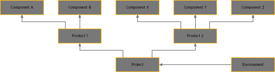
ConTeXt project structure as a flow chart
Here is the complete code. Note that this is Mark II code, and so must be compiled with texexec. If somebody more experienced with the chart module can give separate colors to the project, product, component, and environment boxes, that would be excellent.
\usemodule      [chart]
\setupcolors    [state=start, system=rgb]

\definecolor    [green]  [r=.720, g=1, b=.72] % pale green
\definecolor    [pink]  [g=.720, r=1, b=.72] % pale red
\definecolor    [blue]  [g=.720, b=1, g=.72] % pale blue

\setupFLOWcharts
    [height=4\bodyfontsize,
     maxwidth=\textwidth,
     offset=none]

\setupFLOWlines
    [corner=rectangular,
     color=black]

\setupFLOWshapes
    [framecolor=black,
     background=color,
     backgroundcolor=green]

\startTEXpage
\startFLOWchart[projekte]
    \startFLOWcell
        \name   {project}
        \location   {3,3}
        \connection[rl] {environment1}
        \text   {\ssb Project}
    \stopFLOWcell
    \startFLOWcell
        \name   {environment2}
        \location   {5,2}
        \text   {\ssb Product-specific \\ environment}
    \stopFLOWcell
    \startFLOWcell
        \name   {environment1}
        \location   {5,3}
        \text   {\ssb Project-wide \\ environment}
    \stopFLOWcell

    \startFLOWcell
        \name   {product1}
        \location   {1,1}
        %\connection[tb]    {comp11}
        %\connection[ptb] {comp12}
        \location   {2,2}
        \connection[ntb]    {comp11}
        \connection[tb] {comp12}
        \connection[btn]    {project}
        \text   {\ssb Product 1}
    \stopFLOWcell
    \startFLOWcell
        \name   {product2}
        \location   {4,2}
        \connection[ntb]    {comp21}
        \connection[tb]     {comp22}
        \connection[ptb]    {comp23}
        \connection[btp]    {project}
        \connection[rl]    {environment2}
        \text   {\ssb Product 2}
    \stopFLOWcell

    \startFLOWcell
        \name   {comp11}
        \location   {1,1}
        \text   {\ssb Component A}
    \stopFLOWcell
    \startFLOWcell
        \name   {comp12}
        \location   {2,1}
        \text   {\ssb Component B}
    \stopFLOWcell
    \startFLOWcell
        \name   {comp21}
        \location   {3,1}
        \text   {\ssb Component X}
    \stopFLOWcell
    \startFLOWcell
        \name   {comp22}
        \location   {4,1}
        \text   {\ssb Component Y}
    \stopFLOWcell
    \startFLOWcell
        \name   {comp23}
        \location   {5,1}
        \text   {\ssb Component Z}
    \stopFLOWcell
\stopFLOWchart

\FLOWchart[projekte]

\stopTEXpage
File history
Click on a date/time to view the file as it appeared at that time.
| Date/Time | Thumbnail | Dimensions | User | Comment | |
|---|---|---|---|---|---|
| current | 12:03, 7 August 2012 | 720 × 204 (85 KB) | Esteis (talk | contribs) | Arrow direction: make A --> B mean 'A invokes B' Resolution: 720 px to fit the main content column Colors: nicer | |
| 13:01, 28 July 2004 | 888 × 235 (3 KB) | Hraban (talk | contribs) | ConTeXt project structure as flow chart |
You cannot overwrite this file.
File usage
The following page uses this file: